| |
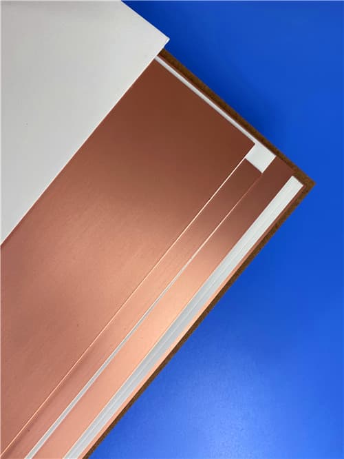
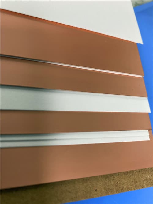
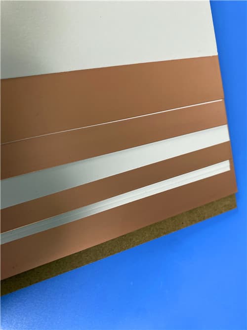
Rogers RT/duroid 6202 DK2.94 Df0.0015 (0.005-0.060") PTFE Ceramic Laminate
Brief Introduction
RT/duroid 6202 is a PTFE/ceramic laminate designed for high-frequency circuit applications. It offers a dielectric constant of 2.94 ±0.04 and a dissipation factor of 0.0015 at 10 GHz. The material provides excellent thermal stability with a thermal coefficient of dielectric constant of +5 ppm/°C, making it ideal for applications requiring consistent electrical performance across a wide temperature range.
Technical Features & Benefits
- Dielectric Constant: 2.94 ±0.04 (for thicknesses ≥0.020")
- Note: 0.005" laminates: 3.06 ±0.04
- Note: 0.010" and 0.015" laminates: 3.02 ±0.04
- Low dissipation factor: 0.0015 @ 10 GHz
- Excellent thermal stability: TCDk +5 ppm/°C (-50°C to +150°C)
- Very low moisture absorption: 0.04%
- High thermal conductivity: 0.68 W/m/K
- UL 94 V-0 flammability rating
- Lead-free process compatible
- Excellent dimensional stability

Typical Properties: Rogers RT/duroid 6202
| Property |
Typical Value |
Direction |
Units |
Conditions |
Test Method |
| Electrical Properties | | | | | |
| Dielectric Constant εr | 2.94 ± 0.04 [3] | Z | - | 10 GHz/23°C | IPC-TM-650, 2.5.5.5 |
| Dissipation Factor, Tan δ | 0.0015 | Z | - | 10 GHz/23°C | IPC-TM-650, 2.5.5.5 |
| Thermal Coefficient of εr | +5 | Z | ppm/°C | 10 GHz, -50 to +150°C | IPC-TM-650, 2.5.5.5 |
| Volume Resistivity | 10⁶ | Z | MΩ·cm | A | ASTM D257 |
| Surface Resistivity | 10⁹ | | MΩ | A | ASTM D257 |
| Mechanical Properties | | | | | |
| Tensile Modulus | 1007 (146) | X, Y | MPa (kpsi) | 23°C | ASTM D638 |
| Ultimate Stress | 30 (4.3) | X, Y | MPa (kpsi) | 23°C | ASTM D638 |
| Ultimate Strain | 4.9 | X, Y | % | 23°C | ASTM D638 |
| Compressive Modulus | 1035 (150) | Z | MPa (kpsi) | | ASTM D638 |
| Copper Peel Strength | 9.1 (1.6) | | lbs/in (N/mm) | | IPC-TM-650 2.4.8 |
| Dimensional Stability | 0.07 | X, Y | mm/m (mil/inch) | after etch + E2/150°C | IPC-TM-650, 2.4.39 |
| Thermal Properties | | | | | |
| Coefficient of Thermal Expansion | 15 | X | ppm/°C | -55 to 288°C | IPC-TM-650 2.4.41 |
| 15 | Y | ppm/°C | -55 to 288°C | |
| 30 | Z | ppm/°C | -55 to 288°C | |
| Thermal Conductivity | 0.68 | | W/m/K | 80°C | ASTM C518 |
| Td | 500 | | °C | | ASTM D3850 |
| Physical Properties | | | | | |
| Moisture Absorption | 0.04 | | % | D23/24, D48/50 | IPC-TM-650, 2.6.2.1 / ASTM D570 |
| Density | 2.1 | | g/cm³ | | ASTM D792 |
| Specific Heat | 0.93 (0.22) | | J/g/K (BTU/lb/°F) | | Calculated |
| Flammability | V-0 | | | | UL 94 |
| Lead-Free Process Compatible | YES |
NOTES:
[1] SI units given first, with other frequently used units in parentheses
[2] References: internal TRs 3824, 5016, 5017, 5035. Tests were at 23°C unless otherwise noted.
[3] Due to construction limitations:
- 0.005" laminates: Dk = 3.06 ± 0.04
- 0.010" and 0.015" laminates: Dk = 3.02 ± 0.04
- ≥0.020" laminates: Dk = 2.94 ± 0.04
Application Areas
- Microwave circuits
- Aerospace and defense systems
- Satellite communications
- Phased array antennas
- High-reliability RF components
- Military electronics
- Base station infrastructure
- Automotive radar systems
Available Configurations
- Standard Thicknesses:
- 0.005" (0.127 mm) +/- 0.0005"
- 0.020" (0.508 mm) +/- 0.0010"
- 0.030" (0.762 mm) +/- 0.0010"
- *Additional non-standard thicknesses available from 0.005" to 0.060" in varying increments*
- Standard Panel Sizes:
- 12" x 18" (305 mm x 457 mm)
- 24" x 18" (610 mm x 457 mm)
- Additional panel sizes available upon request
- Standard Claddings:
- Electrodeposited Copper Foil:
- ½ oz (18µm) HH/HH
- 1 oz (35µm) H1/H1
- Rolled Copper Foil:
- ½ oz (18µm) 5R/5R
- 1 oz (35µm) 1R/1R
- Additional claddings and cladding weights available, such as resistive foil and reverse treated ED
|
|


.jpg)
